
Prestress
Q: The values of prestress for the two main beams, to what stage of prestressing do they correspond?
- Working prestress, i.e. after all losses?
- Initial prestress, i.e. before losses?
A: This is initial prestressing force. Hence, the stress in the strands before release. The working prestress is up to the contestants to decide.
Prestress in crossbeam
Q: From the photograph of the experiment and the drawings it is suggested that prestressing is applied in the crossbeam in the direction perpendicular to the main beam. Is this correct and if so, how much prestress is applied?
A: At the intermediate support, we applied a prestressing bar in the transverse direction with no prestressing force applied. This is to mimic the confinement of the transverse end cross beam of the real bridge.
Loading Protocol
Q: Regarding your response "...clear evidence that a plastic hinge has formed globally", does this mean that for local yielding of the top reinforcement which does not have a substantial effect on the global load-displacement response, the loading protocol of Jack 2 won't be activated.
A: This is correct. The loading protocol of Jack 2 is activated when a substantial effect on the global load-displacement response of Jack 2 is observed. It is not activated at local yielding.
Loading protocol
Q: Regarding the loading protocol of Jack 2, was yielding of the reinforcement monitored in both layers of the flexural reinforcement in the topping? For example, was Jack 2 fixed in case of yielding of the bottom layer (with diameter 12 mm in both tests) while the top layer (diameter 20 mm or 25 mm) was not yielding yet?
A: The yielding of the reinforcement is monitored through a set of LVDT's above the intermediate support, connected to the concrete surface. The loading protocol of Jack 2 is activated if we have clear evidence that a plastic hinge has formed globally.
Measured displacements
Q: It looks that the displacements, as measured under the loading point 1, include the settlement of the supports. This means not only the elastomer bearings but also the testing supporting system. What is the reference of this measurement? It may be the testing floor, loading frame, etc.... Please confirm.
A: This is indeed the case, the deflection includes the displacement of the elastomeric bearings. The displacement is measured by a laser placed on the lab floor, so this can also taken as the measure reference.
Loading protocol
Q: If the flexural reinforcement yields before shear failure, the displacement of the hydraulic jack P2 will be constrained (No further displacement will be allowed)." Is this correct, or will the force be kept constant after the yielding of the reinforcement (over the middle support), as it is schematically shown in the Fig. 5 (b)?
A: Yes this is correct, no further displacements will be allowed. The figure 5 (b) assumes ideal plastic behaviour, but in the experiment the force of loading jack 2 can increase if hardening occurs.
Failure mode
Q: What do you mean with "failure mode"?
A: With failure mode we mean: The mechanism that leads to the loss of structural integrity at the value of "P1, failure"
Team composition
Q: How many members can be in the team?
A: There is no specific limit on the amount of team members. Please be aware that there are certain restrictions on the number of submissions.
Concrete model
Q: Could you please share the concrete damage plasticity model for the beam?
A: It is up to the contestants to come up with appropriate material input parameters for the chosen modelling approach
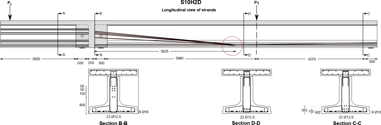
Prestressing strands in beam S10H2D
Q: The number of strands at 60 mm from the bottom is 12 in section B-B and 14 in section C-C, however, it is not shown where the additional 2 strands have been bent downwards.
A: Two strands located 60 mm from the bottom are bent up at the location near section D-D ( 5625 mm from the end of the main girder). The modified drawing showing the strands' longitudinal view is given below. The drawing can also be found in the download section.
Additional Note:
- Two strands located at 185 mm in section C-C are bent down to 110 mm level toward the loading point P1.
Dimension of the topping and precast girder zone
Q: What are the sectional dimensions between the topping and precast girder?
A: The dimensions are shown in the figure below.
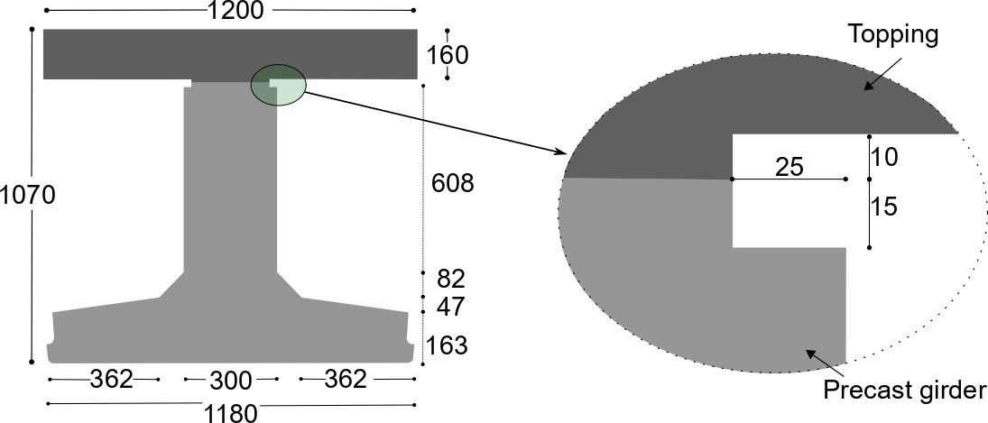
Dimensions are in mm.
Mechanical properties of rebar (diameter - 10 mm)
Q: Please provide the test result of the 10 mm diameter rebar.
A: The average test results of the diameter 10 mm rebar is presented below.
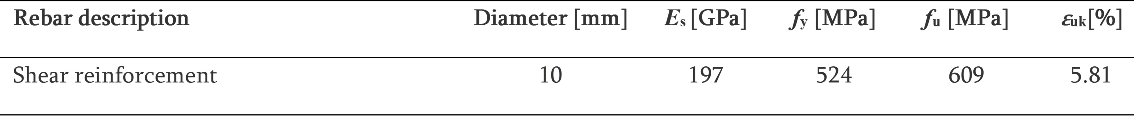
Note: Four samples are tested with coefficient of variation of 4.1%.
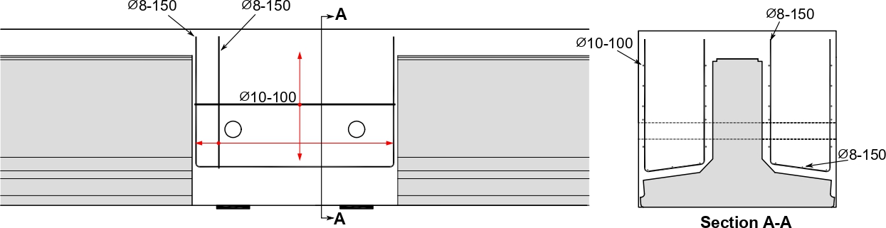
Reinforcement in the cross beam
Q : What type of reinforcement are used in the crossbeam?
A: Surface reinforcements are used in the cross beam; the details are shown in Figure below. 35 mm of concrete cover is used for the cross beam.
Tensile strength of concrete
- The age of the samples at testing is between 150 to 200 days.
- The tensile strength shows a relatively higher scatter. Participants may use the test results or other methods to determine the tensile strength.
Idealized bilinear curve - definition of P1,cr
Q: With P1,cr you mean the first crack under the load P1 or anyhwere over the length of the beams? Please clarify.
A: P1,cr is defined by a significant stiffness change of the specimen. The significant stiffness change could be from cracking of concrete surrounding the tensile reinforcement under load P1 or anyplace over the length of the girder.
Concrete strength at prestress strand release
Q : What is the compressive strength of the concrete at the time of prestress strand release?
A : The compressive strength on day 1 (see Table 1) represents the strength of concrete when prestress was applied.
Loading location
Q: The loading location on the short girder (P2) is not shown in the detailed drawings
A: Both the location of the loadings (P1 and P2) are given in the specimen description file.
Additional Note:
- In the detailed structural drawing, the reference line used for the reinforcement layout might not be in line with the center line of loading P1.
- The location of the loading point (both P1 and P2 ) shall be referred from the specimen description file (Figure 1) .
Additional Details
Q : Please provide sectional drawing near the main load (P1) for beam S10H2D and the position of the longitudinal reinforcement in the top flange?
A: Supplementary sectional detail and top-layer reinforcement descriptions are updated to the structural drawing (check on the download section).
Q&A
Keep an eye on this page as it is updated on regular bases!
-
Information

- Q&A