
Construction stages of the specimens
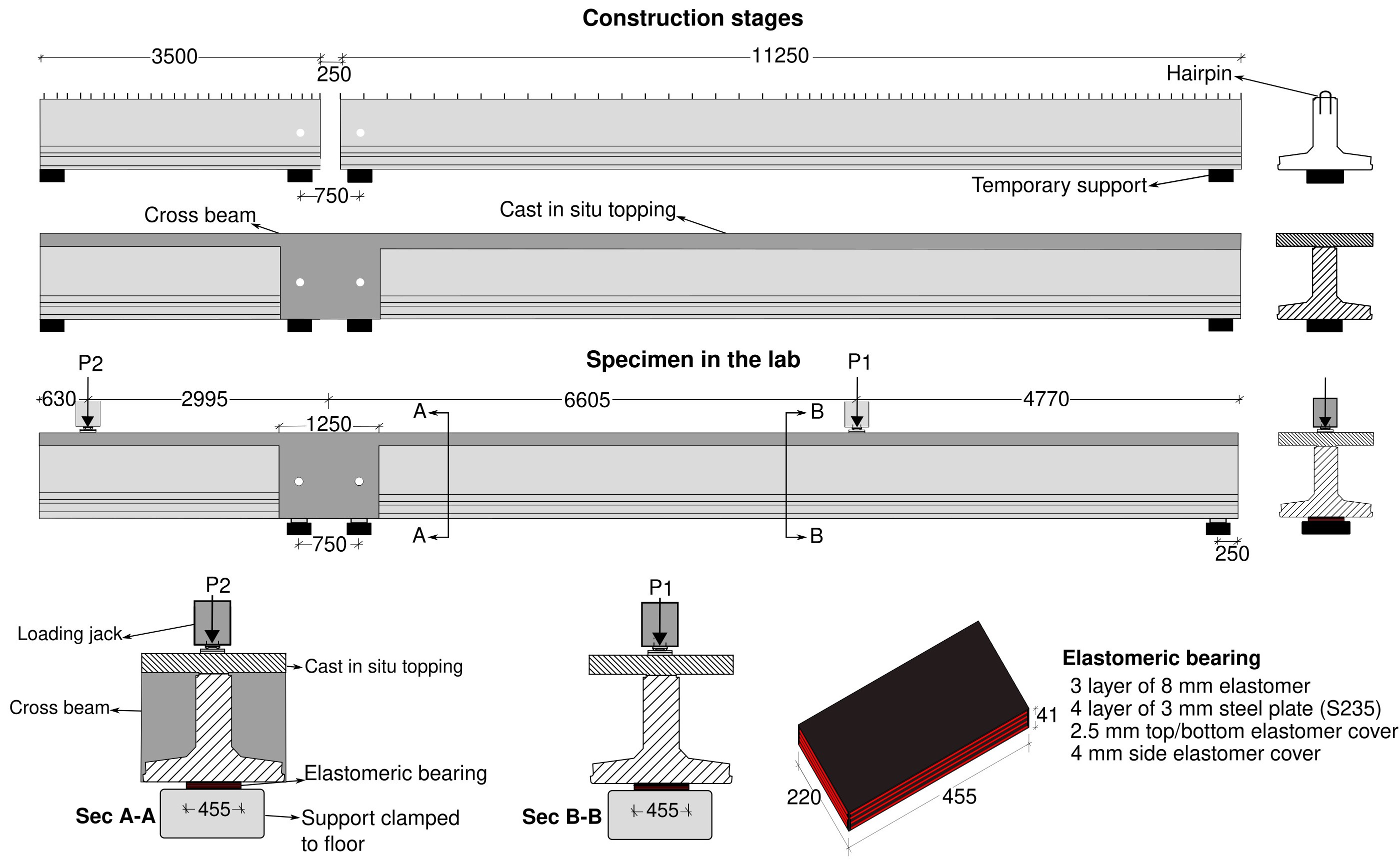
The proposed specimens are connected by of two precast concrete beams with a length of 11.25 m and 3.50 m respectively. The two beams are individually casted in a precast factory, and they are later made continuous using cast-in-situ topping and cross beam. The construction stages and supporting conditions during the production of the specimens is shown in Figure 1.
At the interface between the prefab beams and the cast-in-situ topping, interface reinforcement with inverted U-shaped are used (hereafter referred as Hairpin). Immediately after casting, large aggregates with maximum diameter of 32 mm are spread on the top surface of the precast beams to create a sufficient rough surface (see Figure 2). This interface can be categorized as a rough surface according to de definition of NEN-EN 1992-1-1 Eurocode 2 clause 6.2.5 (2).
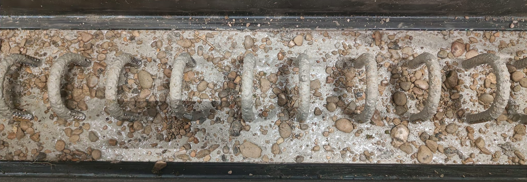
Figure 2: Interface treatment and hairpin reinforcement
Details of selected specimens
Out of the larger research program, the two specimens that are selected for the blind prediction are S10H1A and S10H2D. They share the same geometries and concrete mixture but have different reinforcement and strands layouts.
The longer beams of the two specimens have different strands layout and prestress levels. S10H1A has a straight strands layout with individual strand loaded till 79.0 kN. S10H2D has a fan-shaped strands layout with individual strand loaded till 118.5 kN.
The short beams (cantilever beam) of both specimens are identical. They have a larger amount of prestress and shear reinforcement in the web. Each strand of the shorter beams was loaded till 118.5 kN. As such, shear failure is prevented in the cantilever part.
Two different concrete cover thicknesses are used in the precast beam and topping concrete. 60 mm concrete cover thickness is used for the web of the girder. 35 mm of concrete cover is used in the remaining parts of the girder and the cast-in-situ topping. Additional details of the girders and the topping layer are provided in the download page.
Material properties
Concrete
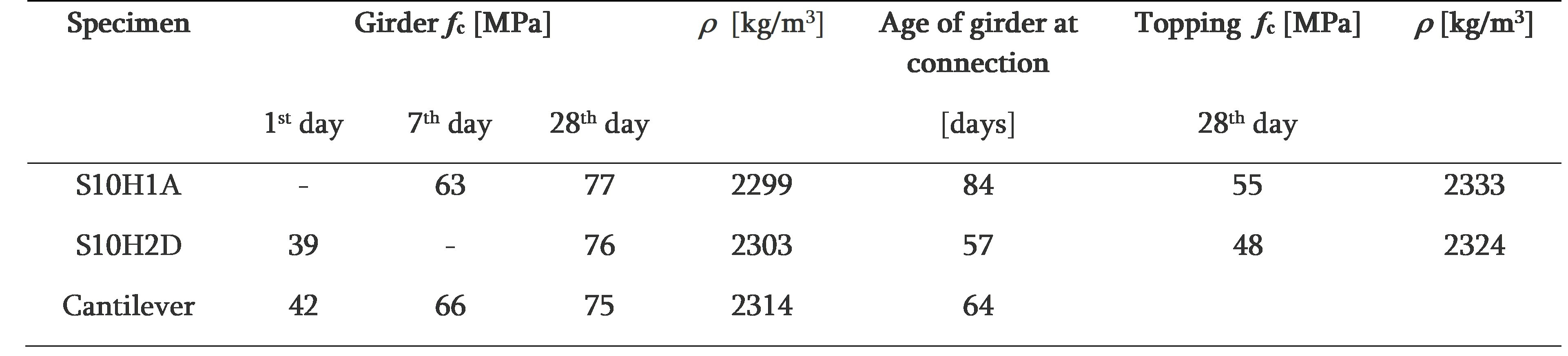
The precast beams are cast at a precast factory in the Netherlands using self-compacting concrete mix. They are then made continuous later by a different contractor. The concrete mixture of the cast-in-situ topping and cross beams is different from that of the precast beams. The compressive strength of concrete was determined using 150 mm cube samples. Table 1 presents the compressive strength of the concrete used in the two specimens and the corresponding age of the concrete. Note that the compressive strength on day 1 is representative to the strength of concrete when prestress was applied. S10H1A uses the same mixture as S10H2D and the cantilever beam, thus one may expect compatible strength for S10H1A.
Table 1- Compressive strength of concrete and cast dates
Additional information:
- River gravel aggregate (Dmax= 16mm) is used for both concrete mixes (girder and topping).
- The expected age of concrete in the precast beams at testing will be 150 days for S10H1A and 210 days for S10H2D approximately. (Here we only count from the casting date of the main beam.)
Reinforcement steel and prestressing strands
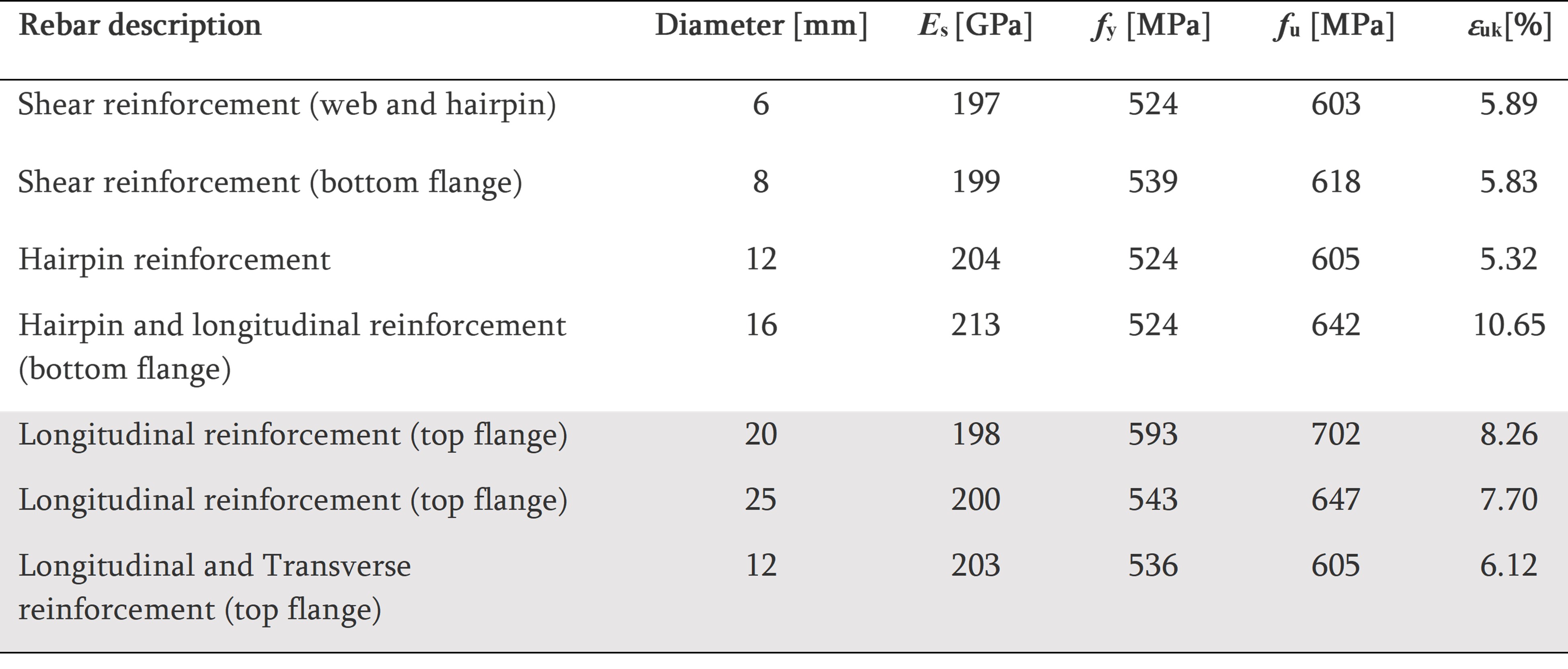
Steel rebars with grade of B500B is used for all the longitudinal and shear reinforcement. Table 2 provides the mechanical properties of all the reinforcements tested at TU Delft Stevin lab.
Table 2 - Mechanical properties of reinforcement bars
The precast beams are prestressed with 7-wire prestressing strand (FeP 1860) having a diameter of 12.9 mm. The mechanical properties of the prestress strands from the technical specification is given in Table 3.
Table 3 - Mechanical properties of prestressing strands
Test setup and loading protocol
A sketch of the boundary conditions of the experiment is given in Figure 1. The specimen is supported at the intermediate and end support using elastomeric bridge bearings. The dimensions of the bearings are 220 x 455 x 41mm (see Figure 1). Three layers of 8 mm elastomer (NR) are reinforced with four steel plates (S235) with a thickness of 3 mm. The design of the elastomeric bearings comply with NEN-EN 1337-3.
The loads on the specimens will be applied using two hydraulic jacks marked as P1 and P2 (see Figure 3). Steel loading plates with 300 × 300 × 20 mm dimensions are used to introduce the force to the specimen. Teflon sheet is placed between the hydraulic jack plate and the steel loading plate . A felt layer of 1 cm thickness is included between the top surface of the girder and the loading plate to distribute the load to the rough concrete surface evenly (See Figure 4).
Figure 3: Specimens in the lab
Figure 4: Details of the loading condition
In both tests, jack P1 was driven by displacement control loading with a constant loading rate of 0.02 mm/s. Jack P2 was driven by force control loading. The magnitude of P2 is based on the real-time reads of jack P1. A constant loading ratio of P1: P2 = 1:0.63 will be maintained until shear failure or yielding of the flexural reinforcement in the topping at the intermediate support region is observed. If the flexural reinforcement yields before shear failure, the displacement of the hydraulic jack P2 will be constrained (No further displacement will be allowed). Additional loading up to the failure will be applied by increasing the displacement in the main jack, P1. Figure 5 presents the scheme of loading plans considering both cases.
 |
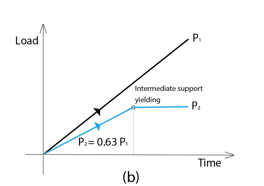 |
Figure 5: Loading plan for case (a) without yielding of intermediate support (b) with yielding of intermediate support
Detail drawing of the specimens can be downloaded from the download section.